
From Chaos to Clarity: Exorcising RF Interference in Audio Systems

Out for a walk or commute? Listen to this article instead!
What are Radio Frequencies?
Merriam-Webster defines Radio Frequency (RF) as “any of the electromagnetic wave frequencies that lie in the range extending from below 3 kilohertz to about 300 gigahertz and that include the frequencies used for communications signals or radar signals.” RF exists all around us, all the time. The Earth itself emits RF that varies throughout the day and by geography. For example, lightning can generate RF in the Very Low Frequency (VLF) to Extremely Low Frequency (ELF) bands. Audio has used RF effectively over the years, eliminating long cable runs for easier wireless connections—radio being one of the earliest adopters of this technology.
Audio Frequency vs Radio Frequency
We use the word “frequency” a lot in literature surrounding sound, so before we conflate Radio Frequency and Audio Frequency, let me offer a distinction. Radio frequencies are a type of electromagnetic wave (or radio wave) that can travel even when there is no medium. This is how we can transmit information back and forth from space stations, past the vacuum of space. Sound waves, on the other hand, are mechanical waves that cannot travel without a medium. These are physical vibrations of the medium through which they travel, like air or water.
Frequency Bands
RF is classified according to frequency bands for practical use, efficient regulation, and application (humanity’s penchant to organize chaos triumphs yet again).
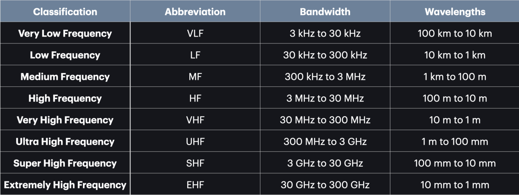
Radio Frequency Classification
Current professional audio systems generally use the UHF bandwidth. I remember a time when we still used VHF systems, which were riddled with interference due to the narrow bandwidth inherent in VHF and required longer antennas than UHF systems. Fast forward to today: systems are more complex, with much more robust coordination abilities. That does not mean effortless and trouble-free transmission at all times. Human errors can still make a good system work at sub-par capabilities. We will look at some best practices, but first, a quick look at some common phenomena that cause wireless issues.
Interference
Multi-Path Interference
Also known as multipath propagation or multipath fading, this phenomenon occurs when a transmitted signal reaches the receiver via multiple paths instead of a single direct line. This happens because radio waves can reflect, refract, diffract, or scatter off obstacles in the space, such as walls, pillars, and chandeliers. These multiple copies of the same signal arrive at slightly different times due to varying path lengths, leading to interference when they combine at the receiver. Like sound waves, if the radio waves arrive in phase at the receiving antenna, they will sum, giving you a strong signal. If they are out of phase, they cancel, resulting in fading (sudden drop in signal strength, “dead zones,” or intermittent connections) or distortion.
Noise Floor
The noise floor refers to the cumulative level of background radio frequency signals (unwanted noise) in a given environment, which includes natural sources (e.g., thermal noise from electronics or atmospheric noise) and artificial sources (e.g., overlapping signals from other devices). As mentioned before, radio waves are all around us, especially in the current age where wireless connectivity is ubiquitous. You can think of this as the baseline level of unwanted noise measured in dBm (decibels relative to one milliwatt). For your desired signal to work effectively, it needs a healthy signal-to-noise ratio (SNR). This value can vary depending on the modulation scheme, receiver sensitivity, and data rate. The general noise floor found in urban environments measures between -90 to -70 dBm. While many wireless systems do not explicitly state the effective SNR, a healthy target should be between 20-30 dB above the measured noise floor.
Intermodulation Distortion
Intermodulation Distortion (IMD) can be described as “ghost” frequencies (intermodulation products) that manifest as a result of the interaction between two or more frequencies. This happens due to the non-linearity of the systems in question, where the amplifiers do not produce an output that is scaled to the input. In wireless mics, these can fall within the operating band, causing interference or audio artifacts. Why not build amplifiers that are linear? There are limitations to diodes and transistors. At high signal levels or when multiple signals are present, they deviate from linear behaviour, causing distortion.

3rd, 5th and 7th Order Intermod Products
The good news is that intermod products are predictable, albeit a nuisance to calculate. Many systems like Shure and Sennheiser encourage frequency deployment within a group as intermod products have been calculated and accounted for within each group. So if you ever feel like delegating frequencies based off your zodiac sign and lucky numbers, you could be running straight into problems.
Types of Antennas
There are various types of antennas in the pro audio market, and navigating them can be a challenge. When do we use each antenna, and what are the considerations to take into account? For example, the operating frequency (the frequency it is meant to receive) of the device will determine how long an antenna needs to be. Higher frequencies have shorter wavelengths (as shown in the table above) and hence can use shorter antennas. I mentioned before that VHF microphones needed longer antennas because they are in the lower frequency bandwidth compared to UHF systems, and thus their wavelengths are longer. Now that you have that backstory, here are some common antennas you will come across:
Quarter Wave
Omnidirectional in the horizontal plane
One quarter the size of the desired frequency wavelength. E.g., 200 MHz is about 1.5m. So one quarter wavelength will be 0.375m
Must be mounted to a ground plane to act as a reflective "mirror" to form a virtual dipole
Half Wave or Dipole
Omnidirectional in the horizontal plane
Similar length calculation as the quarter wave but doubled. E.g. 200Mhz will be about 0.75m in length
Does not need a ground plane
May be mounted remotely
Theoretical 3dB higher gain than a quarter wave with a typical ground plane (although this is not often realised)
Log Periodic or “Paddle Style”
Array of parallel dipoles of varying lengths mounted on a boom or twin-line feed
Directional. Focused radiation pattern (typically 50–100° beamwidth in horizontal and vertical planes)
Increased sensitivity in front than the sides and rear
Wideband, i.e., equally sensitive to all frequencies within the operating band
4 to 8 dB more gain compared to a quarter-wave with a typical ground plane
Helical
Directional. Usually has a narrower beamwidth than the Log Periodic
Typically, the circumference of one turn is about one wavelength of the operating frequency
Increased sensitivity in front than the sides and rear
Typically 8–12 dB more gain than a quarter-wave with a typical ground plane, thanks to its tight focus and circular polarization.
Antenna Beamwidths
Now that you know what types of antennas you will come across, let’s discuss best practices.
Best Practices
Line of Sight
Keep antennas in line of sight to the transmitter. Keeping them away from walls, pillars, audience, etc., will allow easier transmission of the signals. Human bodies are largely water and absorb RF energy, particularly in the UHF and microwave bands, leading to signal loss. RF acts like light in that it can reflect off surfaces. Meaning, even with obstructions, it could still find its way to its receiver, but you do end up with path loss. Think of the RF signal as a voice shouting across a room filled with furniture and people. If the path is clear, the voice is loud and clear. If there’s a curtain or people in the way, the voice is muffled but still audible (penetration with path loss). If there’s a thick brick wall or a metal door, the voice is barely heard or completely blocked (severe attenuation). Reflections off hard surfaces (like mirrors in the room) can create echoes, making the voice garbled (multipath interference). To hear better, you’d move closer, raise your voice, or find a clearer path—similar to optimizing antenna placement or transmitter power.

Maintain Line of Sight
Antenna Distribution
When using multiple receivers together, consider using an antenna distribution unit like the Shure UA844+ or the RF Venue Distro 4. Allowing multiple antennas from individual receiver units to sit next to each other, otherwise referred to as an antenna farm, can cause the radiation pattern of the antennas to warp due to mutual coupling, resulting in dropouts. In such situations, one antenna can act as a parasitic element, altering the current distribution and impedance of its neighbours. If a dipole antenna is placed independently (dual diversity systems will have two adequately spaced apart in its 19” form factor to avoid self-coupling), it will radiate in an omnidirectional pattern. When another antenna is moved close to it, its omnidirectional pattern is compromised. Eventually, you will lose audio, momentarily or not, if the transmitter (handheld microphone or belt-pack) moves into the dead zones.

Avoid Antenna Farms (Left)
Minimum Distance
It may seem proactive to keep the transmitters and receivers as close as possible to each other. After all, isn’t a shorter distance better? Not exactly. In the case of omnidirectional antennas like the dipole, observe a minimum distance of between 1 to 3 meters between the transmitter and receiving antenna. For directional antennas (e.g., helical, log-periodic), a reasonable distance should be 3 to 10 meters, depending on transmitter power. This is to mitigate the risk of your transmitter overloading the receiver’s front end (especially true with directional high-gain antennas). Overloading your receiver could result in distortion, increased intermodulation interference (especially in multi-channel systems), and raise the noise floor, causing degraded audio signals. Imagine shouting into someone’s ears at close proximity. That results in the listener experiencing pain due to the high SPL and experiencing hearing loss, temporary or otherwise. Antenna patterns are also distorted in the near field, meaning they are still irregular and may have weak spots. Having transmitters too close could result in them entering these areas of irregularity.
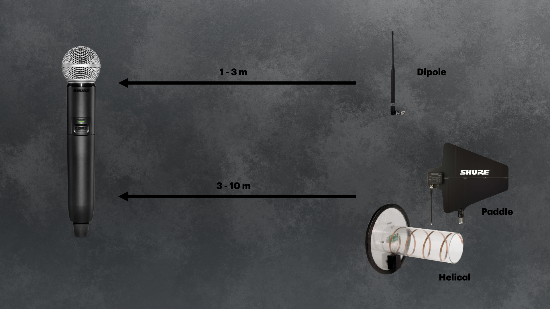
Minimum Distance between Transmitters and Receiving Antennas
Orient Antennas Appropriately
I spoke about the various distribution patterns of the different types of antennas and mentioned that monopole and dipole antennas are omni-directional in the horizontal plane. Which means, should you orient the antennas horizontally, you could have transmitters in the null of the receiver’s polarisation pattern. Having the receiving and transmitting antennas in different planes can lead to polarisation mismatch, resulting in drop outs. It is advisable to orient the receiving antenna in the same plane as the transmitting antenna. For example, a monopole antenna positioned vertically will work best when the handheld transmitter is also positioned vertically, both being in the same plane. However, in real world situations, this is near impossible to achieve. Singers will move around the stage and the handheld transmitter will move along with them. A healthy compromise will be to start with a V-configuration, one antenna at 45° and another at 315° angles (angle between antennas will be 90°), for dual diversity systems. This helps put the receiving antenna in a more neutral plane to the transmitters as it prevents extreme mismatches. A 45° mismatch will result in 3dB loss and a 90° mismatch will result in a 20 to 30db loss. The V-shaped configuration limits this mismatch to 45°, give or take, which keeps signal loss to 3dB or less.
Locate Dual-Diversity Antennas Adequate Distance Apart
I have come across, on multiple occasions, dual diversity antennas mounted on a stereo microphone bar too close to each other. While this may not always cause issues, it is not best practice. Diversity systems rely on independent signal paths to combat fading (e.g., due to multipath or obstructions). Close spacing correlates the signals, diminishing the ability to switch to a stronger path. This results in mutual coupling, meaning the antennas lose their independence and act as a single antenna, negating the dual-diversity design. A healthy distance should be between a quarter wavelength to one wavelength of the operating frequency, for either log-periodic or dipole antennas. This would mean 15 to 60 cm apart at 500 MHz. Dual-diversity antennas spaced further apart adds complexity but doesn’t necessarily improve performance.
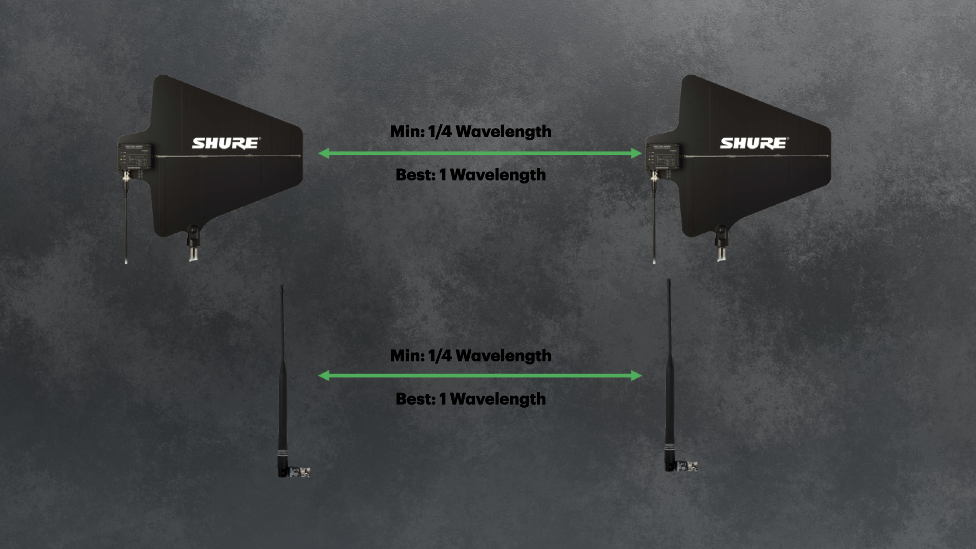
Maintain Adequate Distance for Dual Diversity Systems
Coordinate Frequencies
Scanning the RF environment in the event space to account for noise floor and any stray signals that could disrupt your event is highly recommended. Ideally, this should be done before rehearsals and again before doors open. Brands like Shure and Sennheiser have free-to-download software like the Wireless Work Bench and Wireless Systems Manager that allow users to effectively scan and coordinate frequencies for their wireless devices. This helps eliminate guesswork in coordinating frequencies and gives an overview of the RF environment within the devices’ operating bandwidth. Where possible, as mentioned before, frequencies in multi-system setups should be deployed from within a group to mitigate the risk of intermodulation products. The software mentioned is robust enough to account for such risks. However, they are brand-specific and require the relevant hardware networked together for it to work (i.e., WWB for Shure systems, WSM for Sennheiser systems). For a brand-agnostic device, one that you can carry into any space to scan the environment with, RF Explorer offers some solutions. But do note that this option would require manual frequency selection or additional software for IMD coordination.
The Round Up
Mastering wireless RF systems is as much about understanding the science as it is about applying practical know-how. By recognizing the sources of interference, appreciating the nuances of antenna types and placement, and leveraging the tools for frequency coordination, you can greatly reduce the risk of dropouts and disruptions. While the landscape of wireless technology continues to evolve, the core principles of careful planning, regular system checks, and informed troubleshooting remain timeless. I do hope this gives you some idea on how to exorcise the demons in wireless audio and deliver reliable, high-quality sound for your events.